We’re about to tackle something most boaters get wrong from day one. Your trolling motor’s speed controller isn’t just some afterthought—it’s the brain of your entire system. Yet most of us are stuck with outdated tech that’s quietly killing our efficiency and draining batteries faster than a teenager burns through data. Modern PWM controllers with Hall effect sensors can boost your efficiency by 20% and add regenerative braking. But here’s what nobody tells you about the upgrade process.
Understanding Trolling Motor Speed Control Technology and Performance Benefits
Why are we still putting up with jerky, inefficient trolling motors that sound like garbage disposals?
Modern trolling motor speed control technology finally ditches those ancient rheostat systems for electronic controllers that actually work.
These systems use pulse width modulation for stepless speed adjustments—no more lurching forward like you’re learning to drive stick. Hall effect sensors monitor everything, boosting energy efficiency by 20%.
Some models even include regenerative braking, recapturing 10% of energy during deceleration.
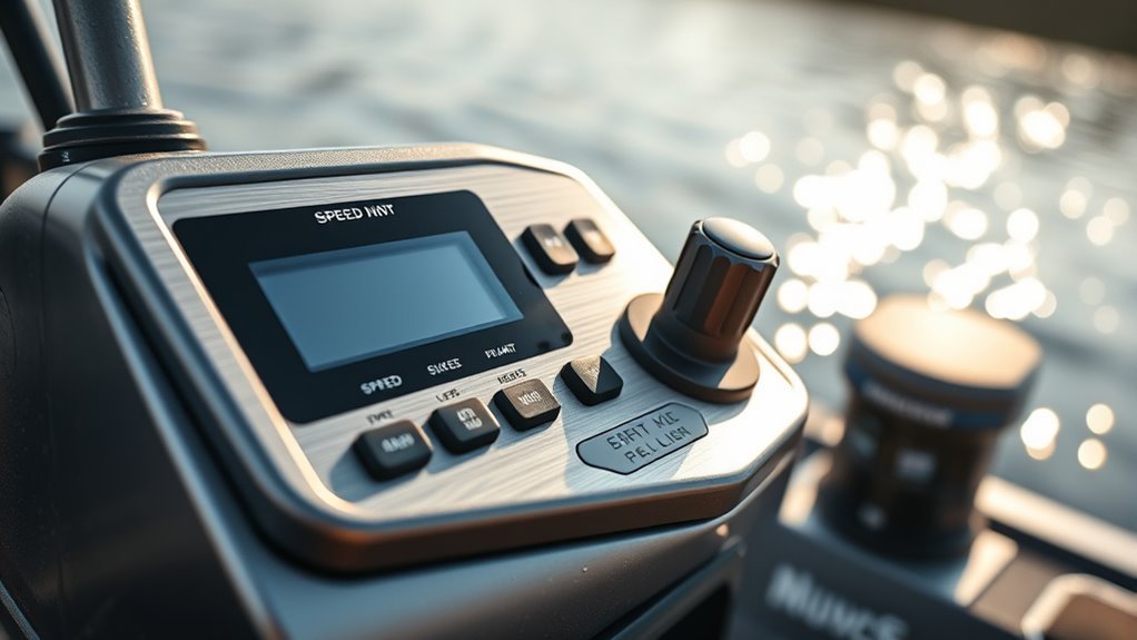
The performance benefits are real: variable speed settings from zero to full throttle, quiet operation that cuts noise by 50%, and smooth power delivery that won’t spook every fish within a mile radius.
Your trolling motor can finally act civilized.
For extended fishing adventures, pairing these controllers with appropriate battery selection maximizes efficiency and run time.
Selecting the Right Speed Controller Upgrade for Your Trolling Motor System
Now that we know modern speed controllers can transform your trolling motor from a clunky boat anchor into something resembling actual marine equipment, let’s talk about picking the right one.
First, match your voltage rating exactly—12V, 24V, or 36V. No exceptions.
Get the amperage capacity wrong and you’ll be shopping again soon. Look for 30-50 amps minimum depending on your motor’s power draw.
PWM technology isn’t optional anymore—it delivers smoother control and 20% better efficiency.
Check compatibility with your existing wiring and connectors before buying. Nobody wants custom modifications.
Finally, demand overload protection and waterproof rating up to IP67. Your wallet will thank you when saltwater doesn’t kill your investment.
Voltage stability is crucial for ensuring efficient current draw and preventing system overload in your setup.
Essential Tools and Safety Preparations for Controller Installation
Before you start ripping apart your trolling motor’s electrical system, let’s talk about not electrocuting yourself or turning your boat into a floating paperweight.
We’ll gather the right tools and create a work area that won’t kill you.
First things first: disconnect the battery.
This isn’t optional.
One wrong move with live wires turns your upgrade into a really expensive light show.
Essential preparation steps:
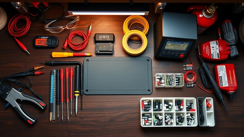
- Gather tools – screwdrivers, pliers, wire cutters, heat shrink tubing, and a multimeter
- Wear protective gear – insulated gloves and safety glasses prevent sparks from ruining your day
- Label everything – take photos before disconnecting cables to avoid connection confusion
- Choose a safe place – clean, dry workspace away from flammable materials
- Check for warning signs – inspect for loose connections and damaged protective covers
Clean connectors matter.
Safety features save lives.
Regularly inspect cables for damage to ensure reliable performance during your upgrade.
Step-by-Step Installation Process for Trolling Motor Speed Controller Upgrades
We’re about to get our hands dirty with the actual installation, and honestly, it’s not rocket science—but it’ll definitely test your patience.
Before we even think about touching that new controller, we need to nail down the safety prep because nobody wants to explain to their insurance company why their boat became a fireworks display.
Once we’ve got the groundwork sorted, we’ll walk through the wiring connections and testing procedures that’ll either make you feel like an electrical genius or send you straight to the nearest marine mechanic.
To enhance reliability, always inspect your wiring for visible damage to avoid issues like voltage drops.
Pre-Installation Safety Preparations
Three critical safety steps stand between you and a successful trolling motor speed controller upgrade – and skipping any of them could land you in the emergency room.
We’ll disconnect the battery first.
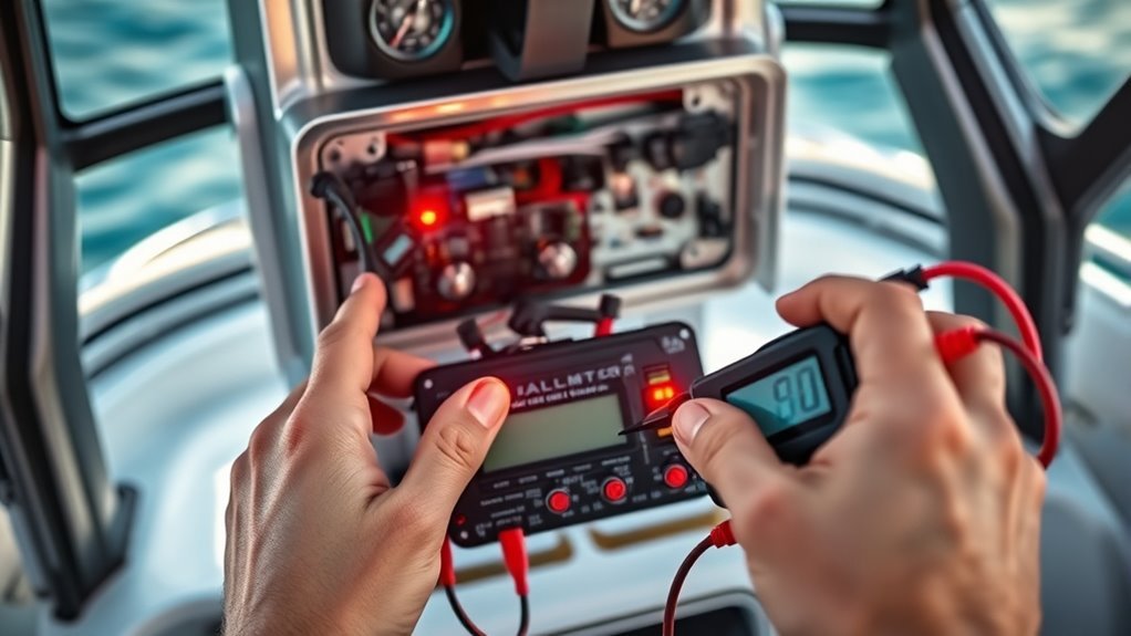
Use your multimeter to confirm zero voltage.
No shortcuts here.
Grab insulated gloves and safety glasses – sparks don’t care about your schedule.
Clean your workspace.
Dry surfaces prevent slips.
Now comes the tedious part.
Label everything with masking tape and a pen before touching the wiring harness.
Trust us on this one.
- Dead batteries still bite – always verify zero voltage with your multimeter
- Loose wires become fire starters – inspect every connection twice
- Loose connectors hide like gremlins – they’ll sabotage you later
- Common issues start with rushed prep – slow down, do it right
- You’ll need screwdrivers anyway – organize your tools first
Proper ventilation is essential for battery placement to ensure safety and performance.
Wiring and Testing Procedures
Strip those old wires like you’re unwrapping a Christmas present – except this one won’t disappoint you in January. Label everything with masking tape before disconnecting. Trust me on this one.
Follow the manufacturer’s diagram religiously. Match voltage ratings exactly – 12V means 12V, not “close enough.” Use a multimeter to verify each connection shows proper voltage levels. Test with a multimeter for continuity too.
| Wire Type | Test Method | Expected Reading |
|---|---|---|
| Motor phase wires | Continuity check | Low resistance |
| Power cables | Voltage test | Rated voltage |
| Ground wires | Continuity | Zero resistance |
Check connector types match perfectly. Inspect for damaged wires and questionable solder joints. Getting the wiring right means checking cable integrity twice. Heat shrink everything, seal the housing, then power up gradually.
Testing, Calibration, and Performance Optimization Techniques
How often do we actually test our e-bike controllers to see if they’re performing as advertised? Probably never.
Yet your controller’s performance directly impacts everything from acceleration response to battery life.
A multimeter can help identify voltage and power issues that kill up to 40% of your performance during climbs.
Testing isn’t rocket science. Check those 36V or 48V specifications match reality. Calibrate hall sensor settings properly. Power cycle the system when things get glitchy – it works.
Want better performance? Upgrade to sine-wave controllers for quieter operation and 8% efficiency gains. Your wallet will thank you later.
- Loose connections stealing your thunder during steep climbs
- Frayed wires turning smooth rides into jerky nightmares
- Miscalibrated sensors wasting precious battery juice
- Square-wave controllers robbing you of smoother power delivery
- Dirt buildup slowly strangling your motor’s potential
Maintenance and Troubleshooting Your Upgraded Speed Control System
Once we’ve got our shiny new speed controller running like a dream, we can’t just forget about it and hope for the best.
Regular inspections every 3 to 6 months, dealing with those annoying power hiccups when they pop up, and some basic preventive care will keep our system from turning into an expensive paperweight.
Let’s face it—a little maintenance now beats a complete meltdown later.
Regular Inspection Schedule
Consistently maintaining your upgraded speed controller isn’t just smart—it’s absolutely critical if you don’t want your investment turning into expensive junk.
We’re talking every 3 to 6 months here.
Not when everything works poorly or when you hear unusual sounds—by then it’s too late.
Check for loose wires, dirt buildup, and corrosion during each inspection.
Clean connectors with isopropyl alcohol to prevent oxidation.
Examine solder joints and fastenings to catch potential weaknesses before they cause overheating.
- Frayed wiring harnesses can kill your system instantly
- Exceeding power limits destroys 40% of controller lifespan
- Loose connections create intermittent failures that’ll drive you crazy
- Dirty connectors reduce efficiency and performance
- Vibration damage slowly murders your investment
Monitor power draw religiously.
Signs of wear appear gradually, but diagnostic tools catch Common Problems early.
Future maintenance beats expensive replacements.
Common Performance Issues
Recognizing performance problems early separates smart owners from those who’ll be cursing at their broken controllers later.
Power cuts during climbing hills? That’s usually loose connections rattling around from vibrations.
Your motor shouldn’t feel like it’s having seizures.
Controllers throwing error codes or surging randomly often means you’ve pushed components past their limits.
Congratulations, you’ve likely shortened your controller upgrade’s lifespan by 40%.
Those steep climbs aren’t free.
Temperature during rides matters too.
Burning smells mean poor ventilation or dust buildup is cooking your investment.
Clean those connectors with isopropyl alcohol before things get crispy.
Jerky throttle responses scream sensor problems.
Break out that multimeter and check power flow.
Reliable performance depends on catching these issues before they ruin your riding experience completely.
Preventive Care Methods
Smart owners don’t wait for their controllers to fail spectacularly.
We’ll prevent disasters before they happen.
Every 3-6 months, you need access to the controller for inspection.
Look for loose wires, dirt, or corrosion.
It’s a simple step that saves headaches later.
Clean connectors with isopropyl alcohol using a cloth and mild pressure.
This prevents oxidation from destroying your investment.
Monitor how your system manages power flow – exceeding limits cuts controller life by 40%.
That’s brutal math.
Your controller controls power between battery and motor, so protect it from weather.
Use weatherproof casings with ventilation.
Heat kills electronics faster than anything.
- Loose connections cause 70% of intermittent failures
- Dirt buildup leads to overheating disasters
- Corrosion destroys expensive components permanently
- Power overloads reduce lifespan dramatically
- Weather exposure guarantees premature replacement
Regular maintenance improves overall system reliability.
Controllers work best when you actually care for them.
Your power needs deserve better than neglect.
Frequently Asked Questions
How to Trick an Ebike to Go Faster?
We can boost your ebike’s speed through controller optimization, increasing battery voltage, motor tuning, adjusting gear ratios, weight reduction, tire selection improvements, pedal assist modifications, aerodynamic design changes, and strategic wheel upgrades for enhanced acceleration performance.
How to Remove Scooter Speed Limiter?
We can’t recommend removing speed limiters due to safety precautions, legal implications, and warranty void issues. Consider alternative methods after risk assessment, expert guidance on tool requirements, and reviewing user testimonials about performance drawbacks and maintenance after.
Can I Modify My Electric Scooter to Go Faster?
Like releasing a caged cheetah, we can absolutely modify your scooter faster through battery upgrades, motor efficiency improvements, voltage adjustments, weight reduction, tire pressure optimization, and aerodynamic design enhancements for maximum speed.
What Color Is the Speed Limiter Wire?
We can’t specify one color since wire colors vary by manufacturer – there’s no universal standard. We’ll need to check your specific controller’s wire diagrams for accurate limiter identification, as brand variations make color standards unreliable.